General Serial Port Basics
A serial port is a physical communication interface through which information transfers in or out one bit at a time. Since the introduction of the Personal Computer in the 80’s, the serial port is used for long distance communication, for example via modems, and communication with peripherals, like industrial automation systems, scientific instruments, point of sale systems, console for servers and network equipment and consumer products like GPS trackers. Implementing serial ports in equipment is still one of the easiest and cheapest ways to enable control by another computer and the console function of serial port communication is highly standardized and widespread. Most times serial port access require minor configuration and very little supporting software from the host system.
The Serial Stream
The serial port is a full-duplex device: It can send and receive data at the same time using two separated lines for receiving and transmitting data, and separated buffers. It is implement in hardware using a shift-register controlled by a internal clock. Therefor, both, receiver and transmitter, must be configured with the same baudrate. To initiate receiving, the transmitting device initiates with a start bit, followed by the actual data bits. There may either be 5, 6, 7, or 8 data bits, depending on the configuration. Both receiver and the transmitter must be configured in the same way for successful transfer.
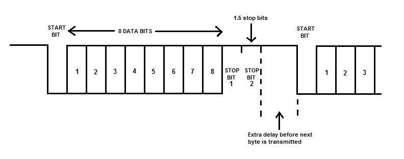
After the data has been transmitted, a stop bit is sent. A stop bit is a mark state before a new start bit can be created. Stop bits can be 1, 1.5, or 2 bit periods in length.
The RS-232 Connector (DB-9 version)
RS-232 is a standard for serial communication and transmission of data and titled “Interface Between Data Terminal Equipment (DTE) and Data Circuit-Terminating Equipment (DCE) Employing Serial Binary Data Interchange”. The serial ports on most computers use a subset of this standard, as the RS-232 standard specifies a 25-pin connector, while most serial PC connectors only have 9 pins.
The RS-232 standard is defined for long distance communication, so it not only defines data signal lines, but also control lines. Two terms are important in this context: DTE and DCE to define the direction of the control lines. A computer is normally used as DTE. The DTE device uses a male connector and DCE a female connector. A cable between those devices is a straight pin-for-pin connection.
Carrier Detect (CD) - incoming
Received Data (RD) - incoming
Transmitted Data (TD) - outgoing
Data Terminal Ready (DTR) - outgoing
Electrical Ground
Data Set Ready (DSR) - incoming
Request To Send (RTS) - outgoing
Clear To Send (CTS) - incoming
Ring Indicator (RI) - incoming
The Carrier Detect is used by a modem to signal that it has a made a connection with another modem. In case no carrier is available, the serial data is used to send commands to the modem.
The Received Data and Transmit Data are the actual communication wires. In case of the RD line, it is incoming on the DTE, and the DCE should keep it in the mark (stop bit) condition till it sends a byte. For the TD line, the DCE is the sender.
The Request To Send and Clear To Send lines are used when hardware flow control is enabled in both the DTE and DTE devices. The DTE device puts this line in a mark condition to tell the DCE device that it is ready and able to receive data. If the DTE device is not able to receive data (typically because its receive buffer is almost full), it will put this line in the space condition as a signal to the DCE to stop sending data. When the DTE device is ready to receive more data (i.e. after data has been removed from its receive buffer), it will place this line back in the mark condition. The complement of the RTS wire is CTS. The DCE device puts this line in a mark condition to tell the DTE device that it is ready to receive the data. This flow control can also be implemented in software, called Xon/XOff or “software” flow control. Software flow control uses special control characters transmitted from one device to another to tell the other device to stop or start sending data. With software flow control the RTS and CTS lines are not normally used.
The Data Terminal Ready and Data Set Ready are intended for the same functionality as RTS/CTS.
The Ring Indicator is toggled by the modem if it receives an incoming call.
The Loop Back
A serial loop back is a cable where all data from the PC is directly send back to it. This cable is useful for testing a serial connection, i.e. if the software stack is really sending data, or to test if the hardware is really working. A loop back can be easily constructed by just connecting pin 2 and pin 3 of the DB-9 connector, however, if handshake signals are involved a slightly more complex cable should be used:
The Null Modem
The Null Modem is a cable to connect a DTE device to another DTE device, in other words, to make a connection between to PC’s using the serial device. The Null Modem cable swaps the incoming and outgoing singles and a “poor man’s” version is just to cross lines 2 a 3 and connect pin 5 straight. In case control flow signals are involved the following cable should be used: